ME360
Product Design
The following work was done mostly in class and was to be submitted as in-class assignments for participation purposes.
Martin Michael Dimo
Modernizing Modern Art
Cartesian Motion System
Motivation: Apply the concepts and methods of ME360 to design a motion system with 2.5 degrees of freedom. The entire system, with subsystems and actuators, needs to be designed and built by our team.
Learning Objectives: Throughout this project, the following objectives are relevant:
-
To devise different ways to embody ideal joints such as revolute, prismatic, spherical, and/or universal joints.
-
To design mechanical components with rational shapes, considering their function, mechanical loading, required accuracy, method of fabrication, and assembly.
-
To integrate and test a product prototype with mechanical and electrical components.
Given Task: To create a mechanical system with 2.5 degrees of freedom with a working volume of 2.5 inches cubed. The system needs to be built small and light enough to be easily carried in a backpack and needs to be designed to be totally or partially disassembled for transport. The actuator and end goal of the system is entirely up to each team, meaning that we were given creative freedom in what the cartesian motion was destined to do.
Considerations: The parts we were given comprise 8020 aluminum, stepper motors, pulleys, and belts (idler and timing). The 8020 aluminum is extruded in standard dimensions: 25 mm by 25 mm. The aluminum extrusion will serve as both structural material and linear guide, which minimizes machining operations by doubling functionality. Except for the standard components, we will design all parts for 3D printing or laser cutting. Additionally, standard fasteners such as screws, pins, and others may be used.

8020 Aluminum with tapped center bores

Small reduction stepper motors

Stepper motors

GT2 timing belt and pulley
Part Design Process: The 3D modeling of parts was done chronologically from the base upwards. That means that we perfected the designs for the motor stands before beginning the design of the marker holder. This might be an inefficient strategy for a large-scale project, but given the time frame we were working with, it allotted just the right amount of time for every part. Below, you can see CAD renderings of the main 3D printed components. They are shown in order of complexity, with the marker actuator being the most intricate and requiring the most amount of fine-tuning. Each part is named intuitively with its function, and every part has been iterated.


Slotted sliders attached to timing belt


Motor holders for two different linear drives


GT2 Pulley stand and marker actuator
System Design Process: The system itself also went through many design phases, beginning with drafting sketches before being constructed. The following sequence of images shows a progressive timeline of the system being built to completion.


Initial proprietary engineering sketches of one linear stage (left) and full system (right)


A rough layout of 8020 aluminum bars and placement of motors

Construction of the first working linear stage consisting of a stepper motor, motor holder timing belt and pulley, pulley stand, and 8020 aluminum bar

Video of working linear stage

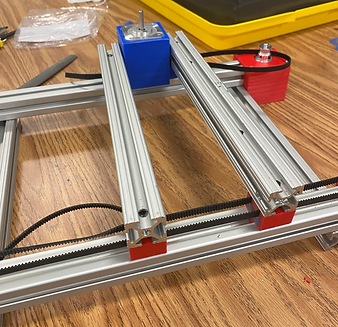
Building of the second stage containing the second linear direction


Final marker actuator with the completed system
(markers were controlled by small reduction stepper motors and imprinted timing belt held together in mechanical compression)

Final electronics (MKS ArduinoMEGA)

Video of final programmed painting

